
There is a hurdle that many engineering departments have cleared over the past few decades but many others out there still need to make the jump.
Manufacturing people have been there all along.
This blog post examines the concept of a Part, why it is so important to PLM and the reasons it can be tough for some people to get used to it.

Where Do Parts Come From?
On one assignment I remember asking the veteran Chief Engineer what his main products were. His reply?
“Drawings.”
In a sense he was right; his engineers captured all their design outputs in drawings (documents too but we’ll let that one slide for now). Drawings were created for the benefit of the downstream functions of Procurement, Manufacture, Sales, Service etc. Each part had its drawings and the product was assembled as defined in another separate drawing. Other drawings had lists of all the parts and drawings needed to make the product. This was the case even if the design was originally a CAD model: the CAD tool solemnly created the drawings which were then printed out and checked into the drawing store.
If there was any sort of problem with the design it had to be corrected by changing the drawings – as many drawings as it took.
All this time, Manufacturing people were talking about parts – physical items you could requisition from Stores and supply to the assembly line. So they had to train clever people to translate all that stuff on the drawings into something that made sense on the shop floor.
But with CAD, the design already makes sense on the screen so it seemed a bit wasteful to convert this data to drawings just to keep the people in Manufacturing busy turning them back into Parts.
So the PDM/PLM pioneers did a smart thing – they introduced the “Part” as the central idea in managing electronic design data. In Manufacturing all you need is a part number (not revision – but we’ll come back to that in a later post) and you have a unique part. That’s all fine but the main problem in Engineering is that it’s unlikely that a part can be fully described by just one drawing.
So how does a Part work in PLM? And what IS it anyway?
Taking a PLM Part Apart
You can design a database so that its tables of rows and columns appear as “Objects” with properties. You can think of each Object as a kind of index card. The index cards can be linked together so that you can jump from one to the other. Different types of these index cards represent different types of Object, each type having its own properties.
Some Object types are designed to look after specific files like CAD, drawings and documents. Some just hold data fields and links.
(The links themselves can be considered Objects with properties but that’s another thing to park for now.)
The key Object type is the Part. Other types may include Drawings (and/or Documents). When you connect Objects together they can be visualised in diagrams like the one below.
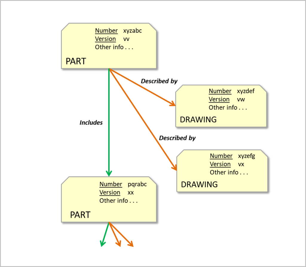
The properties of a Part are likely to include its ID, description, its author and any other general information. The master drawing and document files that describe the Part each have their own index card Objects and all of them can be linked to the Part.
So you can see that the Part itself can have any number of drawings, documents, CAD models and other information to define and describe it. If the Part is linked to other Parts, it is a member of an assembly.
In the diagram, note that the links have direction. This is also an important idea: if you are the Object at the pointy end of the arrow, you are being POINTED AT - there is nothing you can do about it; you are the victim. If you are the object at the blunt end of the arrow, you are the Object DOING the pointing – the perpetrator.
Why is this important? Because what an Object is pointing to is a property of the pointing Object. So to make an Object point at something, you only modify the perpetrator Object - you don’t modify the victim Object. This is fundamental in how Configuration Management works in PLM.
Using PLM Parts
You can create an assembly by pointing a parent Part at all the Parts in the assembly. Some of the child Parts may themselves already be parents of another assembly. Some Parts may be pointed at by more than one parent Part, meaning they appear as children in multiple assemblies.
The PLM system can report on a Part (to the screen, to a file or as a service) and on all its connections including its victim Parts and all THEIR connections. This kind of report replaces the old Parts List. The same reporting service can retrieve all the models and documents at the same time, giving a complete listing of everything you need to fully define the Part, assembly or complete product.
So when someone in Manufacturing sees a Part Number on a physical item or in ERP, this corresponds exactly to a Part in PLM that connects directly with all its drawings, models and documents. Drawings still exist but the Part rules over everything.
And when Engineering says their main output is "Parts", then you know they are Part-Centric.
© Graham Foster 2018
COMING SOON: Configuration Identification.