Blog

The Best Part Numbering Scheme

There are plenty of ways out there of identifying parts and documents, many dating back decades. Some of the most heated and protracted arguments in defining a PLM system are how best to number everything.

  • Should we use a “smart” or a “dumb” numbering system?
  • Can a number include spaces and punctuation?
  • How can we consolidate all the different numbering formats we have inherited over the years?
  • Isn’t it just easier to keep what we have?

This blog post discusses pros and cons and offers why one particular system is my favourite.

 “What’s this new number on here?”; “Hmm – maybe an updated spec?”

Is it worth all the hassle to change numbering systems?

The short answer is “probably not”.

But it may be worth considering, especially if you are consolidating many different legacy numbering systems.  Each case is different but if you are struggling with many different systems inherited from numerous acquisitions, it is worth thinking about.  A new number can be your master ID, with existing parts having aliases to their old numbers.  It will still cause headaches with interfaces to other systems, particularly ERP and for products still in production and support so it is not for the faint-hearted.

So let’s see what purpose numbering should serve.

Configuration Identification

The discipline of Configuration Management was first formalised during the 1960s after proving its worth in early US Air Force missile programs.  It was impossible to know for sure what caused a missile failure if the only evidence was blown to smithereens and cast into the Atlantic Ocean.  What was needed was reliable evidence of the exact build standard of the physical article as tested and the ability to compare it to whatever was authorised by the designers.  Any differences had to be documented.  This was important to separate design problems from build problems.

The term “Configuration Management” (CM) was coined to mean the control of all aspects of information that go into defining a product and the processes to manufacture it.  A Configuration is simply a specific combination of parts and documents.  (Yes, CM also applies to software, even though there is no physical manufacture but for brevity I will leave that one for now.)

To help plan a Configuration Management system, it was split into four areas:

Configuration Identification – How you name and/or number all the bits of stuff you are trying to control, including distinguishing one version from another.

Configuration Control – How to make sure that only people specifically authorised may change the information or the product itself.

Configuration Status Accounting – Defining how you report configurations.

Configuration Audit – How you verify what a configuration is and whether it is correct.

There are plenty of standards documents if you need more details but here I want to focus on Configuration Identification and that means talking about numbering systems.

If you don’t have an explicit, unambiguous way of identifying the information you subject to Configuration Management, none of the rest of CM works.

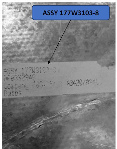
Part Identification can be critical, for example this part number from a piece of seaborne debris identifies it as almost certainly from MH370
(Source: ICAO Investigation Team report)

Dumb not Plain

One of the jobs PLM was designed for was to make Configuration Management easier.  So early PLM adopters were surprised when consultants advised using only plain numbers on parts and documents.  A smart, complicated numbering system was no good as it was second-guessing the PLM system (and was more complicated to implement).  For example, one ID system might include a code that shows a part’s level in the product structure: “0” for end item, “1” for tier 1 etc.  This is a bad idea as it means taking out a new part number if the design is restructured.  And what happens in a flattened manufacturing BOM is anyone’s guess.

But just to have a plain number?  Surely a long, unpunctuated number would itself cause problems; it’s difficult to remember, more susceptible to transcription error and not really giving any clue to what it is – even whether it’s a part or a drawing.

People like to have some structure in a long ID, especially if that structure tells them something about the item.  (We add spaces, brackets and dashes to phone numbers to make them easier to interpret and remember.)

So what we are looking for is a structured configuration ID system that means something but doesn’t get too clever.  But before we look at an example, let’s talk about versions.

Fit, Form and Function

Design Engineers rarely get it right first time.  Even if they do, they always think of some improvement afterwards.  So there is always a later version of a design which has to be differentiated from the earlier ones.  Usually this is done by adding a separate letter or a number after the number itself.  So the later the part’s version, the better it is (or that’s the theory).

So why not always use a new version?  Under what circumstances would you need a complete new part number?  One clue to this can be taken from traditional MRP systems – they ignored the version and just used the part number, assuming all versions with the same part number were interchangeable.  That is to say if you were on an assembly line and picked a part to use from its bin, it could be any version and it wouldn’t matter.

This property of interchangeability means that one version of part must have the same fit, form and function as any other.  If it doesn’t, you need a new part number.

Structured Numbers

So, bearing all that in mind, I present to you my favourite numbering system.  It’s not smart but neither is it plain.  It has structure to help the people on the shop floor but it doesn’t try to be a mini PLM system.

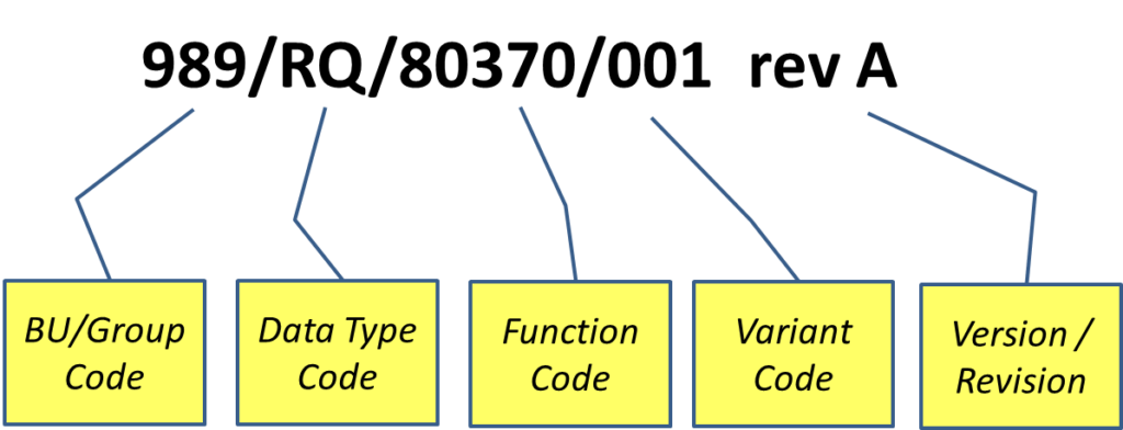
No numbering system is perfect but I really like this one.

Reasons why I like this numbering system:

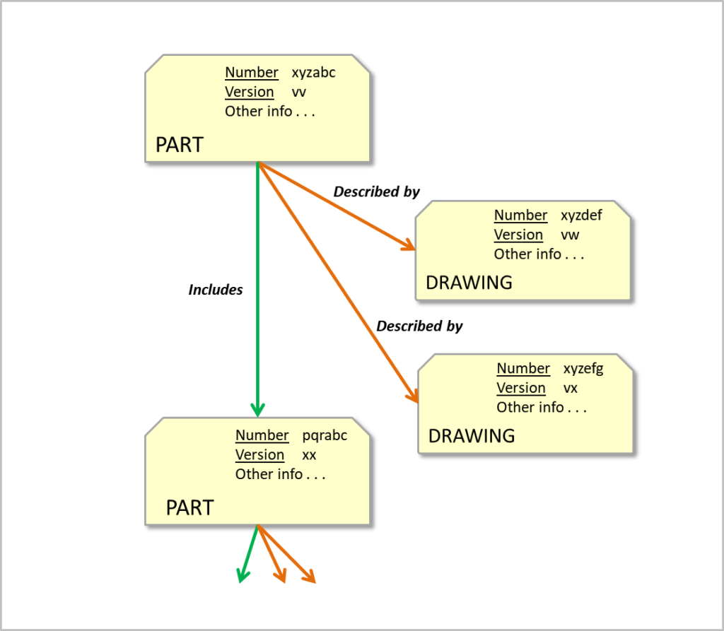
  • It has structure and meaning in terms of identification but no “smartness” e.g. release status or position in product.
  • It allows for separate identities for different types of information so for instance a requirement specification and a packaging drawing and the part itself can have different revisions but still share the same function code.  So a specification can be amended without the need to update the CAD model, installation instructions etc.  What versions of documents go together are defined in, and reported from, the PLM system.
  • It allows Fit, Form and Function re-identification without losing sight of the function.  So if you have an aluminium widget instead of a mild steel widget, the function code for widget can remain the same but with a different variant code.
  • It works for larger organisations by allowing for a Business Unit or Site prefix.  It can also be a CAGE code if required.

So there it is.  I am posing this as my favourite numbering system, but it is not original.  Do you recognise it?  Do you have a better one?  Please let me know using the comment box below.

© Graham Foster 2018

COMING SOON:  Planning for PLM

What does it mean to be “Part-Centric”?

There is a hurdle that many engineering departments have cleared over the past few decades but many others out there still need to make the jump.

Manufacturing people have been there all along.

This blog post examines the concept of a Part, why it is so important to PLM and the reasons it can be tough for some people to get used to it.

Is it a Part, a Model or a Drawing?

Where Do Parts Come From?

On one assignment I remember asking the veteran Chief Engineer what his main products were.  His reply?

“Drawings.”

In a sense he was right; his engineers captured all their design outputs in drawings (documents too but we’ll let that one slide for now).  Drawings were created for the benefit of the downstream functions of Procurement, Manufacture, Sales, Service etc.  Each part had its drawings and the product was assembled as defined in another separate drawing.  Other drawings had lists of all the parts and drawings needed to make the product.  This was the case even if the design was originally a CAD model: the CAD tool solemnly created the drawings which were then printed out and checked into the drawing store.

If there was any sort of problem with the design it had to be corrected by changing the drawings – as many drawings as it took.

All this time, Manufacturing people were talking about parts – physical items you could requisition from Stores and supply to the assembly line.  So they had to train clever people to translate all that stuff on the drawings into something that made sense on the shop floor.

But with CAD, the design already makes sense on the screen so it seemed a bit wasteful to convert this data to drawings just to keep the people in Manufacturing busy turning them back into Parts.

So the PDM/PLM pioneers did a smart thing – they introduced the “Part” as the central idea in managing electronic design data.  In Manufacturing all you need is a part number (not revision – but we’ll come back to that in a later post) and you have a unique part.  That’s all fine but the main problem in Engineering is that it’s unlikely that a part can be fully described by just one drawing.

So how does a Part work in PLM?  And what IS it anyway?

Taking a PLM Part Apart

You can design a database so that its tables of rows and columns appear as “Objects” with properties.  You can think of each Object as a kind of index card.  The index cards can be linked together so that you can jump from one to the other.  Different types of these index cards represent different types of Object, each type having its own properties.

Some Object types are designed to look after specific files like CAD, drawings and documents.  Some just hold data fields and links.

(The links themselves can be considered Objects with properties but that’s another thing to park for now.)

The key Object type is the Part.  Other types may include Drawings (and/or Documents).  When you connect Objects together they can be visualised in diagrams like the one below.

The properties of a Part are likely to include its ID, description, its author and any other general information.  The master drawing and document files that describe the Part each have their own index card Objects and all of them can be linked to the Part.

So you can see that the Part itself can have any number of drawings, documents, CAD models and other information to define and describe it.  If the Part is linked to other Parts, it is a member of an assembly.

In the diagram, note that the links have direction.  This is also an important idea: if you are the Object at the pointy end of the arrow, you are being POINTED AT - there is nothing you can do about it; you are the victim.  If you are the object at the blunt end of the arrow, you are the Object DOING the pointing – the perpetrator.

Why is this important?  Because what an Object is pointing to is a property of the pointing Object.  So to make an Object point at something, you only modify the perpetrator Object - you don’t modify the victim Object.  This is fundamental in how Configuration Management works in PLM.

Using PLM Parts

You can create an assembly by pointing a parent Part at all the Parts in the assembly.  Some of the child Parts may themselves already be parents of another assembly.  Some Parts may be pointed at by more than one parent Part, meaning they appear as children in multiple assemblies.

The PLM system can report on a Part (to the screen, to a file or as a service) and on all its connections including its victim Parts and all THEIR connections.  This kind of report replaces the old Parts List.  The same reporting service can retrieve all the models and documents at the same time, giving a complete listing of everything you need to fully define the Part, assembly or complete product.

So when someone in Manufacturing sees a Part Number on a physical item or in ERP, this corresponds exactly to a Part in PLM that connects directly with all its drawings, models and documents.  Drawings still exist but the Part rules over everything.

And when Engineering says their main output is "Parts", then you know they are Part-Centric.

© Graham Foster 2018

COMING SOON: Configuration Identification.

What is PLM? New Readers Start Here

Those of us who work in Product Lifecycle Management tend to forget the time before we understood PLM or what it’s for.  So when we get asked this type of question it can be a struggle to come up with a user-friendly answer that is not full of jargon.  There are plenty of opaque examples on the Web.

I am as guilty as anyone.

So in this first blog I have set myself the challenge of retelling the PLM story for people who are new to PLM.  This includes managers who delegate anything PLM because they don’t “get it” enough to make informed decisions.

Why was PLM invented?

Products need to be designed and then made.  Engineers and Designers conceive and design the best product they can, they record it using models, drawings and documents and then they hand it over to the people who have to manufacture that product so that the organisation can make the most money.

Then they change their minds.

In the middle of the last century, a designer or engineer wanting to make a change would have to go the Drawing Office (“D.O.”) and beg for the original drawing back so it could be modified.  Forms would be filled in, maybe a change note signed and only then would the custodian release the drawing to allow changes to be made.

But when CAD came along, it allowed the designer to make changes pretty much all the time – the master data was just a file on the designer’s PC and there was no custodian.  The result was errors and confusion because the information that manufacturing was using didn’t always match what the designers considered their latest design.  You couldn’t go back to using the DO because they had all been fired as part of the justification for investing in CAD.

Enter PLM (but called various other things at the time).

What’s inside PLM?

PLM has a thing called a Vault that allows designers to deposit files, each file having its own entry in a database.  Each of these database entries has a status field that represents the approval or release level of the corresponding file in the Vault.  If the release level is low (such as “In Work”) then the database allows the originator to retrieve the file and make changes to it.  If the database entry has a high status level (such as “Released”) this means that too many people downstream are depending on this information so it is more difficult to get the file back.  To make a change, the file has to be copied and given a new identity so as not to disrupt what is already going on downstream.  If the re-identified design proves worthwhile, there are some forms to fill and, if everyone agrees, then the new version can be used.

But wait!  This means that someone has to specify what all the possible status levels are; it would be daft to make them different for every product so best to figure out a standard sequence.  That sequence of status levels represents the Lifecycle of the things in the Vault.  You have to progress from one Lifecycle state to the next and this may involve lots of other people and disciplines to check and approve the move.  In the D.O. days, this was likely done with paper forms.  But our PLM has a database so why not let all the people that need to contribute to each form just login and do it directly in the system?  A Workflow allows people to review material in the system, add information and go/no-go for the next stage in the process.  The fact that all these people may be able to view this original material as it evolves from level to level is in effect a basic form of cross-functional Collaboration.


Most products aren’t defined by just single drawings or CAD models.  Maybe there are complex assemblies or a merging of separate mechanical, electronic and cabling models.  Some way is needed to relate these different things together so they don’t get lost or confused.  This is the role of the Part and its relationships.  In PLM, the Part, a term already common in Manufacturing, is a database entity used to hold properties, to control its file in the Vault and to link to other Parts.

The concept of a Part doesn’t come easily to those used to dealing primarily with drawings and this will be the focus of a future post.

I.T. is no good unless you can get information out of it.  A lot of very valuable information is locked up in the Parts, in the relationships, in the Vault, in the Lifecycle states and in the progress of Workflows.  Reports can be constructed that summarise this information and that makes management more efficient.  Similarly, an ERP Integration can take the product information from PLM and transfer or update a separate manufacturing system so as to avoid someone re-keying everything.

If you store in Part to Part relationships the position and orientation in a 3D co-ordinate space then you can use a Visualisation tool to show and manipulate 3D representations of the Parts together.  In effect this is a virtual mock-up of the evolving product and is a way to see models from different tools to check that everything fits together.

The final element of PLM to deal with in this post is Administration.  The whole system depends on defining users, roles, teams, projects, authority levels, types of Parts, etc. etc.  This can be a complex task with many interrelated factors and getting this right is one of the keys to success.

What about…?

I can hear some readers shouting at the screen: “But what about…” then saying one or more of Configuration Management, As-Built, Service Parts, Parts Catalogues, EBOM to MBOM, Process Breakdown, Functional Breakdown, Embedded Software, Analytics, Security, Programme Management, Dashboards, Augmented Reality, Digital Twin, PLM benefits, adoption and so on.

Well I just mentioned them there.

But any detail now on such topics is not going to help anyone unfamiliar with PLM and is more likely to confuse.

So I am drawing stumps at the basics and leaving the rest to future blog posts.


COMING SOON: What a Part is and what it means to be Part Centric.